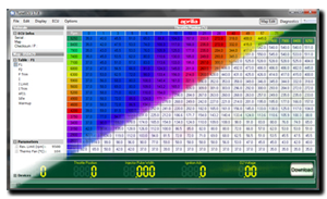
 OBDII … on board diagnostics … essentially, reading and writing data to/from the ECU regarding the running condition of the bike. The Caponord uses the Sagem MC1000 ECU and communicates via the ISO9141 protocol. All very well and good, but how do we talk to it and what does it have to say that’s useful?
Actually, quite a lot and as of November 2010 two packages now exist, the newest is Freeware – TuneECU and the other is TuneBoy. TuneECU offers exactly the same functionality as TuneBoy. Firstly, I’ll look at TuneBoy as this is the one that any other package will be compared to …. or you can skip straight to the review of TuneECU [here].
The TuneBoy package
In the box, you get both diagnostics and map editing programs on a CD and a cable to connect from the bike to a USB port. Although you can use TuneBoy staight out of the box, you will need a ‘key’ to be able to use the TuneEdit software, this is generated from your ECU serial number and is specific to your bike. The software is currently £305 for everything, £244 for the software and cable WITHOUT the key …. and £121 for a key. Basically, it’s expensive and poorly documented … furthermore, from personal experience, there is NO support from the writer. If you do decide to buy, you may find the TuneBoy program does not display some of the data …. if that’s the case, then replace the TuneBoyControl.dll with this one [HERE]. It should all work fine then.
Please note, my screenshots differ slightly to the base package … I’ve ‘tuned’ the graphics and layout to be a bit more ‘Aprilia’ and relevant to the Caponord. Email me if you want to know how to do this and I’ll gladly give you the files.
TuneBoy diagnostics
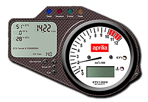 So this is the start-up screen – the Dash. The analogue RPM reads slightly high and frankly this screen isn’t much use for diagnostics. As well as making it look more ‘Aprilia’ I also changed the data slightly – it now displays battery volts instead of speed (only works for Triumphs). From here you have access to three other screens, SENSORS – real time readings from the bike, ERRORS – where error codes are displayed along with a snapshot of other data when the error occurred. Finally, TESTS – where some basic functions on the bike can be activated.
Sensors
So next up, I’ll look at the sensor screen. In this shot, the bike is running and warmed up 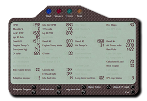 and all the data is as expected.
Points to note here …. the ‘Side Stand Down’ will not toggle while the bike is in neutral. If you want to test this function do it with the engine off and the bike in gear – it’ll work then. It’s not a fault of the software but a quirk of the bikes ‘safety circuit’ design. The last element of the ‘safety circuit’ – the clutch switch, can also be tested with a minor change 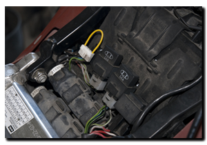 on the bike …. remove the diode block and short pins 1 & 5 together and make sure the bike is in neutral and the side stand is down …. now, when you operate the clutch you will see the ‘Side Stand Down’ digit toggle. Also, the ’00’ displayed in the O² Trim is normal – it never shows anything and if you remove it from the screen the O² Volts stops working! An in-depth explanation of what the data means can be found HERE. The buttons at the bottom of the display allow us to reset the throttle position and make changes to the fuel trim to improve the idle. This is certainly by far the most useful of the screens!
Errors
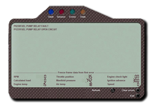
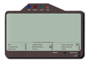 The errors page will list the codes and description that the ECU has logged along with a snapshot of other sensor data from the FIRST recorded fault. The codes can be cleared from here as well. As you can see, a clear screen, just what you want! Error codes conform to the ISO9141 protocol and so even without the text description, you can decipher the displayed fault.
In the next shot, an error code has been generated by removing the fuel pump relay, interestingly it comes up with two fault codes – P0230 & P1231. Along with the fault code, the MIL (EFI) lamp is also activated and a ‘snapshot’ of other perameters is displayed. The fault deciphers as ‘P’ – powertrain, ‘1’ – generic (‘0’ – manufacturer specific), ‘2’ – air or fuel injector circuit and ’30/31′ – Primary or secondary circuit malfunction. At the bottom of the display, we have the ‘reset’ button that will clear all stored error codes and clear the MIL(EFI) light.
Tests
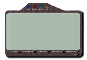 The only things of interest here for Capo owners, is the row of buttons at the bottom. Here we can test the Tacho, cooling fan, Idle Stepper motor and fuel pump operation – only those with EVAP emissions will make use of the ‘Test Purge Valve’ function … and no European models are fitted with it. Clicking on a button causes that item to cycle or run for approximately 10 seconds and a line of text will appear in the main screen as confirmation of the test status.

