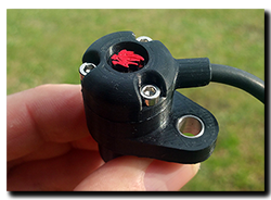
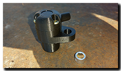
 Yesterday I was asked about the 3D printed speedo sensor case and I couldn’t believe that it’s been almost six months since last mentioning it and about nine months since fitting it. So how is it holding up? Well just fine and dandy thanks for asking!
So far, It’s been through a long 40C summer and some damn cold nights of recent. Heavy rain and a decent shake down over something like 12,000 miles including some off-road, add up to a pretty good trial all-in-all. The plastic is holding up nicely with no signs of cracks, warping or sun-fade, so it looks like the Color-Fabb nGen material is a good choice for use on the Capo and that is backed up by the frame bungs I made last year – all as good as the day they were fitted.
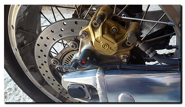
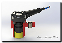
I’ve put a pdf drawing of the main body in the CAD/3D downloads area so you’ve some idea of the dimensions of the speedo sensor. Fitting a sensor from an alternative Aprilia is of course an option, the only real issue being the tight bend in the cable to make it fit, not particularly nice, but functional I guess. Also, is the cable long enough and does it have the right connector? I’ve no idea. Some may want to go with a different sensor altogether, fine in principle as long as it uses the same voltage/current range and the signal is compatible with the dashboard. then of course you have to make it fit, hopefully the drawing will help a little here as it gives depth, diameter and mounting hole location for comparison. Again there is the issue of cable length and connector …….
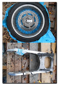
 Just a word of caution though, the standard sensor is a snug fit in the caliper mount and cannot in any way move into the wheel. Can the same be said of an aftermarket sensor and its modified fitment? The consequences of something possibly working loose and jamming the back wheel don’t bear thinking about!
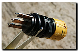
Of course I went for a third option, 3D printing. I’d originally thought of the case as reusable, but in the end, given the few pennies it costs to print I made it a semi-sealed item. The sensor is installed with sealant and after soldering the wires in place, the cap is also back filled with sealant and screwed into place. If and when it fails, I’ll just remove reusable bits (boot, screws etc) and print/assemble another one. Total cost (sensor, case, screws, wire, boot & connector) came in under £30 – Granted about the same as some RSV/SL sensors on ebay …. but that’s new not second-hand!
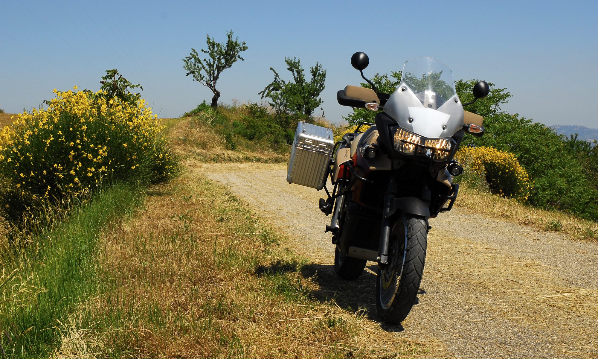
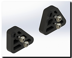
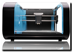 Yesterday, on a rather cold and wet afternoon, moto-abruzzo took a step into the future ……. courtesy of a good friend that I’m doing a project for. A 3D printer arrived! And being the top man that he is, he’s cool about me printing off those odd little Caponord bits-n-bobs.




 So is it worthwhile following this up do you think, or should I resign it to – nice idea but ……?