All I can say is – WOW! Since the link was added to the INNOVV website about the K1 review, I don’t think I’ve ever had so much traffic or comments in one day. Absolutely fantastic and wonderful to swap emails with so many other riders!!
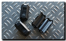
 So as a follow on, today I’ll answer a couple of questions that folks have raised. Firstly, ferrite cores, what are they and what do they do. In a nutshell wires can act as aerials, bringing unwanted high-frequency signals into (or out of) an electrical circuit, such that this interference causes problems. By fitting a clip-on ferrite core you prevent these unwanted signals from entering or leaving – in this case the DV recording unit. In my case for example, when I tapped the horn button (Stebel Nautilus Compact Tuning – 18A!) the DV recorder would always reboot itself. Since fitting the ferrites – no problems at all when using the horn! The ferrites I bought are for 3.5mm cable and fit all the INNOVV wiring just fine.
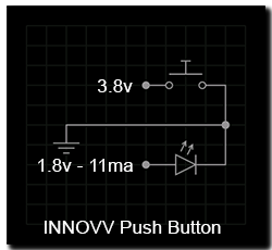
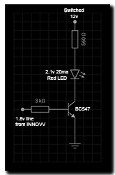
 Secondly, the button/LED replacement I made. Here’s a breakdown of the existing button – just a momentary push-to-make switch and a red LED, nothing more. As mentioned in the previous post, the voltage to the switch is 3.8v and to the LED 1.8v pulling approx. 11ma. The switch could easily be replaced by any momentary switch you like, that’s easy, unfortunately though the LED is drawing very little current and so this line cannot be relied on (without frying something!) to power a brighter LED that would typically draw around 20-30ma, so a new circuit is required. Now this could be as simple as using this line to drive a transistor such as in the diagram below. Here a fused switched 12v line provides the required
  voltage/current to drive an LED via a transistor. In this case the INNOVV provides the 1.8v (at 0.5ma) to switch the transistor. This circuit could all be assembled inline with the LED to save space …… however it would have to be meticulously assembled, if the 12v line touches the 1.8v line, then goodnight DV recorder!! Much better to buy a small box and a piece of strip-board from Maplin (UK) or RadioShack (USA) and build the circuit into the cable run.
Remember that if you want to use a green or blue LED instead of the red one, then the 560Ω resistor will need to be replaced with a 510Ω one to compensate for the different voltage requirement.
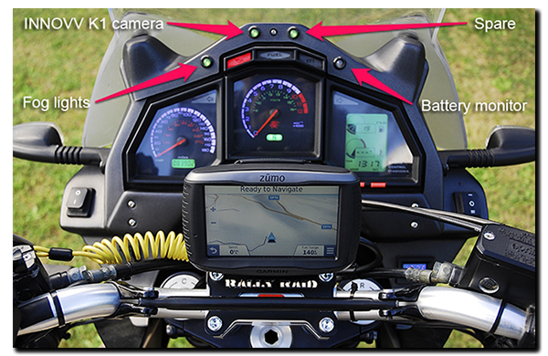
Now this where I admit I didn’t do it this way! That’s because I wanted to add a couple of other functions that I thought were useful, so I went and added a microcontroller into the melting pot. On the standard setup, when the button is pushed (long) the recorder starts or stops and the LED changes state – in other words, I have feedback from the unit while I’m riding along. However when the button is pushed (momentary) the LED does nothing …. the DV unit will say “Video file protected” and the red dot on the recorder screen will change to a yellow triangle with an exclamation mark in it, but I can neither hear or see any of this from the saddle. So for file protect/unprotect I don’t have any usable feedback and I wanted to change that.
Now the microcontroller runs a combined red/green LED – this lights green when recording and off when not recording, if file protect is enabled then it toggles red/green for 0.5 seconds at 10Hz then turns red denoting that the file currently recording is now protected. Another push of the button reverses the process – red/green toggle and then solid green for unprotected file recording.

There is also one other feature ……. when file protection is enabled, it is ONLY for the current file. So if for example you activate file protection with a 10 minute file at 9 minutes 58 seconds elapsed, then 2 seconds later a new file will begin to record and it is UNPROTECTED, see the issue? So now, if I have activated file protection, the microcontroller waits until the new file begins recording and triggers file protection itself in the background and will continue to do so until I deactivate it. All the time I know I’m recording a sequence of protected files because the LED is red not green.
