Almost made it to 100K Km

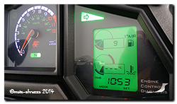
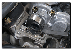
Code 33 - front coilYesterday was a great day, warm and a smooth running Capo to zip about on …… not so today, no siree Bob. Started her up this morning and that dreaded little EFI light started flashing away. Front coil #1 (code 33) had shuffled off to the great coil playground in the sky.

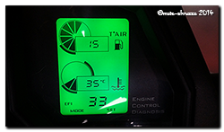
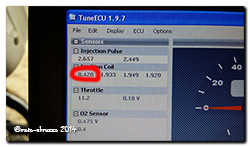
Before swapping it out, I plugged TuneECU in to get a screenshot of the dwell – reading 0.420 in the picture – definitely dead as a Dodo. Not to worry though, a spare was on the Coil #1 reading 0.420 ...... deader than a dead thing.shelf and an hour later the job was well and truly jobbed. Just two things to mention really ….. one, changing that rubber sleeve is a right pain in the proverbial and two, getting the HT lead onto the Amrish coils is even harder! Note to self …. make sure the next spare coil on the shelf is already fitted into a sleeve and has a HT lead attached, that’ll save at least 15 minutes and a book full of swear words! So after 92,413Km the second Sagem coil has been replaced, the first went a couple of years ago, so will the last two make it to the big 100K Km?
Here’s a graphic I keep (laminated) on top of the airbox lid – it just makes it easier to locate the right coil without consulting the manuals. Click for a bigger version.
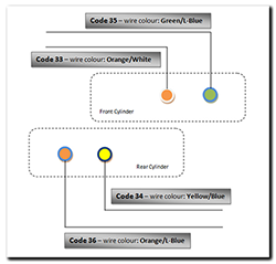
Coil location, colour and numbering

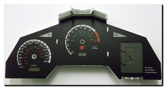
New ‘Lockwood’ inlay fitted at last

Right indicator repeaterOn 4th February Jan came back home with a suitcase fair groaning with all manner of goodies. The most eagerly awaited though, was the pair of new inlays from Lockwood International Ltd. So first impressions?

Excellent! From the textured material to the bleed-free printing, from the fit to the light-transmission …. everything was exactly as I’d hoped. The first thing I did was pop one onto a waiting chassis/board and turn on the lighting – did the text and colour match the light channels? Again, perfectly. Now I could relax, prepare the new chassis and get ready to fit one permanently to the dashboard. To fix it in place I decided to use a general-purpose spray adhesive and did a trial run on an old chassis/inlay to make sure it would be suitable. Everything seemed fine and it was certainly good experience to do a dummy run.

Making sure the chassis was grease and dust free was essential, then masking off the light-channels, mounting pegs and anywhere else I didn’t want spray glue to go! A couple of thin coats of adhesive were applied and the inlay fitted 10 minutes later to allow time for the solvents to evaporate. Perfect! It was now ready to be fitted to the circuit board, but first a couple of modifications to the board/processor circuits.

First the eeprom file needed to be updated for the Futura speedo/tacho, then the code in the microcontroller needed updating for the different (voltmeter) needle calibration. At the same time a couple of modifications were made to the circuits based on insights I’d picked up about Arduino boards from the Internet, also the auto-dimming circuit was finally added for the variable back-lighting, a bit of tweaking with the code – and it was all ready to be refitted to the Capo.

So there I was …. on a wind-swept but warm Sunday morning, dashboard in hand and about to see the fruits of a few months work finally come together on the bike. No doubt the code for the auto-dimming will need fine-tuning, but that can be done without removing the dashboard again – and that’s the line in the sand, right there. Once fitted, I shouldn’t have to remove them again anytime soon …. and that’s a great feeling!

I think that about now would be a great time to pause and say thanks to a few folks who have helped me keep the momentum in this little project. Firstly Jan for her patience and for lugging stuff across the continent for me, to Andy (beasthonda) for bouncing ideas around with me and his interest in the project, to Arvdee in the USA without who’s generous donation of a Futura inlay I wouldn’t have had a template.  Last but not least, Clive from Lockwood International for putting the proverbial icing on the cake – thank you all!!!! 😀

Moving along nicely

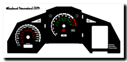
Just got this photo from Clive over at Lockwood International in the UK, the nice folks who have made my new inlays for the Caponord dashboard. I’ll write more when they arrive …… I can’t wait!!

RST Futura based inlay with voltmeter and left/right indicator repeaters

  • Back-lit voltmeter within the tachometer
  • Left & Right indicator repeaters
  • Red-line raised to 10,000rpm to match ECU setting
  • Side-stand lamp is now where the unused ABS lamp was
  • Funky Aprilia lion instead of boring old ‘aprilia’ text
  • ‘magneti marelli’ logo removed …. well they didn’t design this one!

Reading the current situation

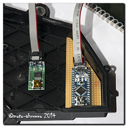
©Lockwood International 2014 - UK Futura inlay with voltmeter, L&R indicators and sidestand lightWith the new inlay nearly complete and sufficient testing of the modified dashboard to prove its reliability in day-to-day use, it’s now time to move on and complete the next stage of miniaturising the circuit board. The big grey box and wiring loom holding the Arduino Uno stays for the time being, but now it will house the smaller circuit board and Arduino Nano. Once thoroughly tested, the box and loom will disappear as the board finally gets mounted inside the case.

Aduino Nano and Pololu 1300 programmerThis time around the microcontroller will be programmed differently to speed up the start time and free up more memory space. For that I’m using a Pololu 1300 programming device ….. Something I’ve never done before, let’s hope I don’t fry it! If all goes well, that then leaves me an Arduino Uno spare and it would be rude not to find another Caponord related little job for it! So here’s the next project…..

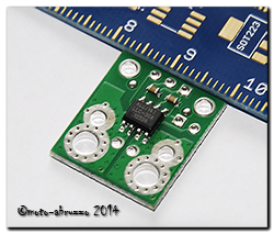
I’ll be installing the Uno and three of these naughty little puppies along with and LCD screen into the redundant grey case. Self-powered, it will measure current flow through the 30A rec/reg fuse and the two main 30A fuses simultaneously. The screen will Pololu ACS714then display measured and calculated data as well as storing the data onto an SD card mounted into the display. So it’ll be a data-logger as well!

The idea is to have the three ACS714 devices, wiring loom and a single multi-pole connector under the saddle. The unit will then simply plug into the connector and merrily measure away. A decent battery and memory card should make data logging for 2hrs + pretty straight forward. So watch this space ………


Lights, camera …….. action!

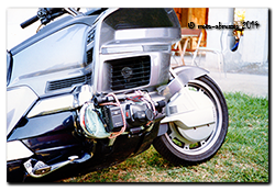
Honda GL1500 with cam-cover-camera!Video on bikes ……. Nothing new of course, it’s been going on for ages. But for what it’s worth, here’s a potted history of moto-abruzzo’s fumbling’s as a videographer.

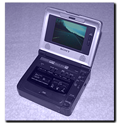
This pic is probably where it all began, back in 1992 on a hot day in Italy when I was bored. I strapped my analog camcorder to the cylinder head of the 1500 Goldwing and had a fun afternoon playing. The low perspective added drama to the shots and I could watch the front end working in corners …. Well as much as you can corner on a Goldwing! But of course the kit was bulky and not waterproof in the slightest, Sony Video Walkman GD-V800so once I’d had a play I never touched it again – especially in the rain soaked confines of the UK.
It was 2001 before I used video again. Now working as a full time Motorcycle Instructor I could see the value of using video as a training aid, so I fitted my Triumph Trophy 1200 with two 720×520 colour bullet cams (front & rear) and used a Sony Video Walkman GD-V800 deck to record. The cameras were interchangeable with PIP (Picture in Picture) so one image was primary while the other was a thumbnail in the corner. It all worked very well and I learned a great deal about camera placement, lens choice, filming and editing video from those days. Sadly, when the Trophy was written off in 2005 the video gear just sat in a corner of the workshop and never got fitted permanently again – mainly because no bike stayed long enough until I got the Caponord!

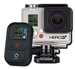
GoPro Hero 3+ BlackAnd that brings me up to date I guess. 2014, a new year and all that jazz, will see moto-abruzzo once again playing with video. Hopefully this time it will add a new perspective to the website and move things in a slightly different direction. After a few weeks of internet-homework, weighing up the pros and cons of some amazing kit, I’ve chosen the GoPro Hero 3+ Black as the camera platform to use. I’m not going to bang on about the camera as a zillion websites and YouTube videos are available to review this kit, it’s enough to say that in comparison to previous kit I’ve used it look fantastic, is a magnitude more advanced and  …….  well lets just say I can’t wait to get filming!
Service time over

Empty tank makes for light work!Service time is over for another 6,000miles. I decided a couple of years ago to extend it from the original 4,650 miles due in part to the well documented stability of the valve clearances and because I’m using the long oil filter and a decent branded oil. Whether I’m being realistic or foolhardy for extending the interval only time will tell.  😕

Valve clearances were all in spec but on the tight-side, so no need just yet to use the new Hotcams shim kit, but next time I’ll change all the shims by ±0.025mm to shift the 0.13mm ...... getting close to the limitgap back into its mid-range. That should see the valves good-to-go for at least another 50k miles. Everything else was absolutely fine, with just a slight tweak of the CO to lean out the idle.

The rest of the bike was given a thorough check over and happily all bearings and seals are fine, a squirt of grease in the rear suspension linkage keeping that nice and smooth. The drive chain and sprockets were cleaned and checked and after 33,333 miles (yes, that’s a genuine number!) they’re still good ….. This is the highest mileage I’ve EVER had from a drive chain. DID ZVM2 chain rocks!

Air filter frolics

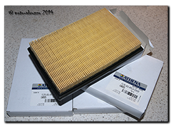
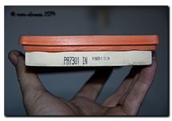
Athena CA8925 air filter to replace Aprilia AP8104169I mentioned recently that I’d ordered a batch of air filters made by Athena in Italy. They’re a direct replacement for the Aprilia AP8104169 one and the only obvious difference is the black foam material instead of orange, and that’s fine and dandy with me. However, on stripping out the old filter I noticed for the first time (that I can recall!), it has a code on the end …. hmmmm ….. could it be a viable manufacturers code I wonder?

Hmmm what's the code mean then Sherlock?A few minutes on the web confirmed that the number is definitely a manufacturers code – not Aprilia, but FIAAM. A bit more digging unearthed a total of three cross-referance numbers. Tecneco AR9474PM, FRAM CA9474 and FIAAM PA7301. The downside? All of them seem to be obsolete, with FRAM/FIAMM saying they went out of production in March 2012! Buggeration ……

But … one of the sites I found listed a filter that is an almost identical footprint to the OEM one:-

Aprilia OEM          210 x 140 x 30

FIAAM PA7180   212 x 140 x 60

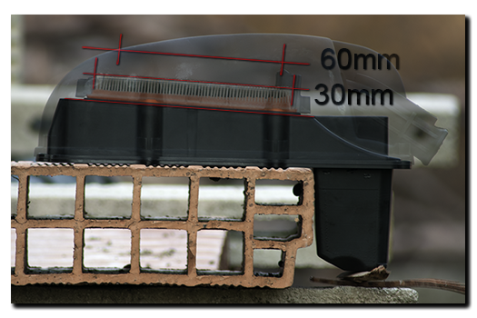
Now a 2mm length difference is peanuts – the OEM one can be stretched/compressed by 10mm easily, the problem may well be the height, at 60mm it’s double the OEM filter. So to try to find out I took some pics of the airbox with the OEM filter in and had a play in Photoshop. Here’s the outcome.

Photoshop airboxThe vertical lines show where the filter ends or interferes with the frame or lid. As you can see, the 60mm high PA7180 will squash in at the ends …… will this be enough to restrict air Athena box label for the Capoflow, or will the greater surface area of the larger pleats compensate? Answers on the back of a crisp £20 note if you please! 😀
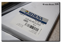
Next time I’m passing a motor-factors, I’ll order one and have a play. At £4.68 each they’re half the price of the Athena …. and that brings me nicely back onto track, the new Athena filters that turned up today. What are they like then eh?Embossed pleats

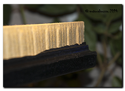
Well, dimensionally it’s an exact copy, so the fit is absolutely fine. One nice touch is the embossed pleats. It keeps them evenly separated for better air flow unlike the OEM element that is simply made of folded paper where the pleats can collapse onto each other. The bottom line is that it fits well, looks better constructed and is substantilly cheaper than OEM (€8.35 each from Germany) …… oh and it comes in a nice shiny box!

Let’s all do the Shimmie-Shimmie Shake …..

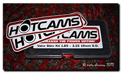
10mm shim kit ...... and stickers!!!It took the best part of three weeks for the valve shim kit to arrive from the USA ….. and I think that’s rather good, considering the surge of Christmas post whizzing around the world, not to mention the holidays themselves getting in the way.

I’d ordered a Hotcams (SHIM-31) 10mm  shim kit (thickness range: 1.85-3.25mm) that’s sold for the HD V-Rod and Buell 1125, but has a whole bunch of shim sizes in it that suit the Capo, or any V990 motor just fine.

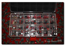
Three shims of each sizeThe V990 engine uses shim sizes from 2.3-3.0mm in 0.025mm increments, so quite a few of the Hotcams kit are redundant, not only that, the kit only contains shims in xx.000mm or xx.050mm sizes, not the xx.025mm and xx.075mm that may be needed. Now this may appear to make the kit a rather poor choice, but look again at what you do get for your money when compared to the shims an Aprilia dealership/stockist will sell you.

So let’s compare ……..

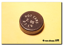
Shim close upHotcams Shim Kit – delivered to Italy was $82.35 / £49.94 / €59.73 including customs duty & taxes. That’s 15 usable shim sizes (x 3 each) and works out at approximately $1.83 / £1.11 /€1.33 per shim. Now compare that with genuine shims from AF1 in the USA – $14.99 each*, or Ultimate Parts in the UK – £9.15-£12.85 each all of course with package and posting on top. I think it’s fair to say that if 50% of the shims are on hand for around 10% of the Aprilia list price …. well I can live with that!

*AF1 do sell a shim kit and it may well be the same one that Hotcams sell. Certainly the range of shims is identical – as is the box by the pictures on the website. Why didn’t I buy from them? Simply price, at $75.99 + $40 shipping, they weren’t even close to Ebay stockist Powersportsplus.

See ya later Indicator

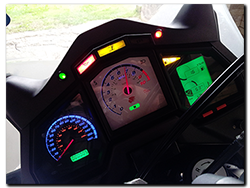
While it rains, rains and rains some more, I’ve had time to complete the mods with respect to moving the warning/tell-tale lighting around on the dashboard. Now the Capo has a nice left AND right indicator repeater lights ….. and looks all the better for it. So to recap.

  1. Unused ABS light is now the side-stand light
  2. The side-stand light is now the low-fuel warning light
  3. The low-fuel warning light has new green LED’s and is now a right-hand indicator repeater.

Here’s another piece of video with all the lights working. You’ll notice that the fuel is already on reserve, hence the old side-stand light (now low-fuel) is on throughout the video. Sorry about the quality, but a dismal dark day and a smartphone don’t work so well together ….. and my cold hands adding the shake didn’t help! I’ll add a new page to the site shortly with details of how the circuits were rearranged.

While I waited for Youtube to upload the video, I took a walk down the road to see what damage had been done by the 24hr+ of solid heavy rain …………

…………. let’s just say the Capo nor the Rangerover are going anywhere soon. We don’t appear to have a road left for about a 30m stretch. It appears to be languishing somewhere down in the valley by the looks of it! Pics tomorrow. 😥

Tacho/Voltmeter live on the Caponord

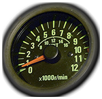
Up and running at lastPhase 1 is over, Phase 2 begins …….. yes, the reworked dashboard with voltmeter/tacho and fade-in/fade-out auto-dimming backlighting is off the workbench and finally onto the Caponord. I know it doesn’t look too inspiring at the moment, but it is only a prototype unit for development. The white tacho face is simply a temporary inlay printed on a piece of A4, so it better not get wet!

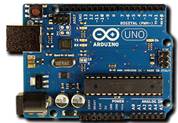
Arduino Uno V3Inside the box lives an Arduino Uno with a homemade interface board that switches and adjusts the signals to/from the dashboard as required. The single connector plugs into an additional fused loom that runs to the battery positive terminal. I’ve tried to build in safeguards against under/over voltage, battery disconnection and reconnection spikes and its own failure with regards to how the dashboard functions, hopefully most if not all eventualities have been covered …. fingers crossed!

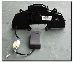
The little grey box .... I’ll run this setup for a while and try to iron out any other issues as they crop up, but what then? Well Phase 3 has already started in parallel with Phase 2! A new microcontroller board that uses the same chip, but with a footprint that is an astonishingly small 8% of the Uno has been ordered. Not only is it small, it also loses the peripheral bits and bobs that I don’t need – and that means much lower power consumption. I’m really hoping to get the whole thing inside the dashboard case if possible, but the worst case scenario will mean a small box fixed directly to the back of the dashboard – so no wiring loom or bulky connectors!

Where the ideas originated ..... the Kwak GT & GPZ's of the 1980/90 eraAs well as getting the inlay reprinted with the added voltmeter graphic, I’ve also decided on a little  re-arrangement of the existing graphics and functions. For example, why oh why is a ‘side-stand’ light prime-center of the display when it already has a safety circuit to stop you riding away with the stand down? ….. Magneti Marelli over-egging the pudding I think.

So the side-stand is moving down to the (unused) ABS lamp spot, the low-fuel then moves up to the side-stand lamp and the low-fuel light then becomes the right-hand indicator – as it should have been all along. Yes, a turn repeater for both left AND right hand signals!!!

Left AND right turn repeater lamps!

With all this in the pipeline, I can now source a decent place to have the new inlay card made. I’ve spoken to a couple of companies in the UK already, but I’ll keep looking around for a little while longer …….. do you know anyone you can recommend? If so, I’d like to hear from you.

 Last but not least, here’s another short piece of video with the panel working on the bike.