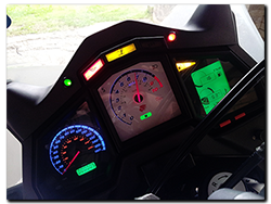
 Phase 1 is over, Phase 2 begins …….. yes, the reworked dashboard with voltmeter/tacho and fade-in/fade-out auto-dimming backlighting is off the workbench and finally onto the Caponord. I know it doesn’t look too inspiring at the moment, but it is only a prototype unit for development. The white tacho face is simply a temporary inlay printed on a piece of A4, so it better not get wet!
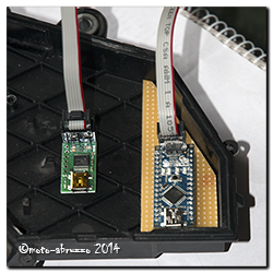
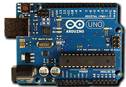 Inside the box lives an Arduino Uno with a homemade interface board that switches and adjusts the signals to/from the dashboard as required. The single connector plugs into an additional fused loom that runs to the battery positive terminal. I’ve tried to build in safeguards against under/over voltage, battery disconnection and reconnection spikes and its own failure with regards to how the dashboard functions, hopefully most if not all eventualities have been covered …. fingers crossed!
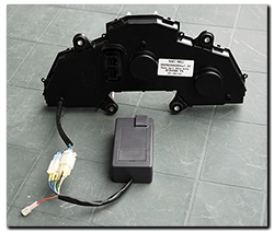 I’ll run this setup for a while and try to iron out any other issues as they crop up, but what then? Well Phase 3 has already started in parallel with Phase 2! A new microcontroller board that uses the same chip, but with a footprint that is an astonishingly small 8% of the Uno has been ordered. Not only is it small, it also loses the peripheral bits and bobs that I don’t need – and that means much lower power consumption. I’m really hoping to get the whole thing inside the dashboard case if possible, but the worst case scenario will mean a small box fixed directly to the back of the dashboard – so no wiring loom or bulky connectors!
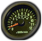 As well as getting the inlay reprinted with the added voltmeter graphic, I’ve also decided on a little re-arrangement of the existing graphics and functions. For example, why oh why is a ‘side-stand’ light prime-center of the display when it already has a safety circuit to stop you riding away with the stand down? ….. Magneti Marelli over-egging the pudding I think.
So the side-stand is moving down to the (unused) ABS lamp spot, the low-fuel then moves up to the side-stand lamp and the low-fuel light then becomes the right-hand indicator – as it should have been all along. Yes, a turn repeater for both left AND right hand signals!!!

With all this in the pipeline, I can now source a decent place to have the new inlay card made. I’ve spoken to a couple of companies in the UK already, but I’ll keep looking around for a little while longer …….. do you know anyone you can recommend? If so, I’d like to hear from you.
Last but not least, here’s another short piece of video with the panel working on the bike.

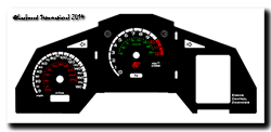


 As well as getting the inlay reprinted with the added voltmeter graphic, I’ve also decided on a little re-arrangement of the existing graphics and functions. For example, why oh why is a ‘side-stand’ light prime-center of the display when it already has a safety circuit to stop you riding away with the stand down? ….. Magneti Marelli over-egging the pudding I think.