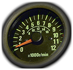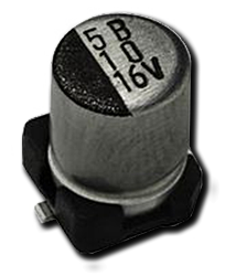
No1 component that fails on a dashboard…..

Yes, today I’m dishing the dirt on the number one bad-boy component on the Caponord and Futura dashboard. Or more to the point, why this sad little part earns this unwanted reputation! What is it? Well it’s a rather innocuous SMD radial electrolytic capacitor rated at 16V 47µF.

Over the past couple of years, I’d say that 70% of contacts via the website have involved this component in one way or another …. and that percentage is steadily increasing! Why? Simply because of the constant and unstoppable tick-tock passage of time. Unlike most electronic components, electrolytic capacitors have a given life span based firmly on operating temperature and duration. What does it do? In a nutshell, it smooths out the 5V DC power rail … without it the rail contains a nasty AC component and that really upsets the microcontroller!

First I want to look at the symptoms this little guy causes when it begins to shuffle off to the electronic afterlife:

  • Dashboard dead except for Oil, Neutral and Side-Stand LED’s – Especially when cold.
  • After sitting in the sun or being heated during a ride-out, it may spring into life, or flicker on and off rapidly. This is the clincher!

Of course, to be 100% sure, we have to get down to the circuit board and identify the component first:
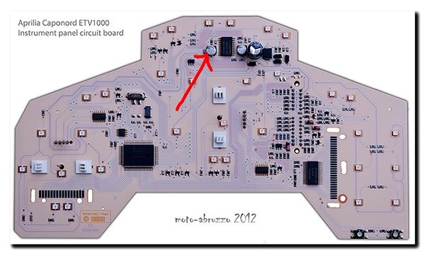
Aprilia Caponord ETV1000 & Futura RST1000 dashboard capacitorSo there it is, just to the left of the voltage regulator chip. Now I’m sure the eagle-eyed amongst you will have noticed that there is a similar (in fact identical) component to the right of the regulator …… why is only the one on the left a problem then?

Well the dashboard has two regulators in the one package, supplying two independent 5V power rails. One is powered permanently from the minute a battery is installed in the bike, the other only operates when the ignition is switched on. And there lies the answer to the question …… lets punch in some numbers. For the sake of argument, we’ve got a Capo that has done 5,000 miles in a year and averaged 50mph.

  • 5,000 miles / 50mph = 100 operating  hours for the right hand (switched) capacitor.
  • 365 days * 24hrs a day = 8,760 operating hours for the left hand (permanent) capacitor.
  • Now lets assume 10 years have passed …. now we have 1,000 / 87,600 operating hours respectively!

And there is the bottom line. After 10 – 16 years on the bike, the left hand capacitor is simply reaching the end of its working life long before its companion on the other power rail, and with each passing year more are failing …. It’s not a case of ‘if’ folks, it’s a simple matter of when!

Replacement is straight forward and has been done by quite a few owners over the years, but like most things, it requires a certain level of skill and experience along with the right tools for the job ….. without these, there is a very real possibility of damaging the tracks or adjacent components and making the board worse than when you started. You have been warned!
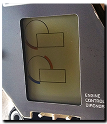
UV and dashboards don’t mix!

Aprilia Caponord ETV1000 Rally-Raid sun damage to dashboard LCDThe youngest Capo dashboards are about 10 years old now, maybe a little older, while the majority including the Futura are knocking on 14 to 16 years old. Every board that I see these days has very poor light output on the Blue LED’s and signs of UV damage to some degree in the lens. Most worrying though is the marked increase in the number now showing UV damage to the large LCD panel.
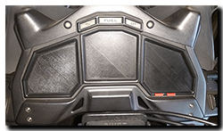
LED’s of course can be replaced, so can the lens if you can stomach the €60 (Wendel Motorräder) or £52 (Fowlers UK) and have plenty of patience while you wait an eternity for it to magically appear. However the LCD panel is a different matter, you’ll need to find a damaged/unserviceable dashboard you can rob or replace the dashboard in its entirety as these parts are unobtainable and were never sold as spares by Aprilia anyway.

Aprilia Caponord ETV1000 Rally-Raid dashboard instrument panel lens cover protection UVFor quite a while now I’ve taken to slinging an old t-shirt over the dash when parked up in an effort to offer it some respite from the elements. Not perfect I know! So a while back it got me thinking about knocking something up on the 3D printer – and here they are. Three panels, 4mm thick with the underside recessed 1.5mm to keep it well away from the lens. A groove runs around the edge to take the same 3mm diameter neoprene seal material (AP8120615) as used between upper and lower airbox halves, so only a thin strip of soft seal actually makes contact with the lens.

Aprilia Caponord ETV1000 Rally-Raid dashboard instrument panel lens protection covers with neopreneIf these turn out to be half-way useful, I might treat them to a layer of Zircoflex heat shield material and replace the flagging heat shield material on the plastic panels over the silencers at the same time!

CGI dashboard – 2

Saturdays lovely sunny weather gave way to thick fog and a definite chill in the air – time then to hunker down on the PC and finish the CGI dashboard and add a couple of extra bits to make it a touch more interesting on the eye.

CGI dashboard – 1

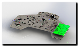
Aprilia Caponord ETV1000 Rally-Raid dashboard, instrument panelSlowly getting more parts of the Capo into CAD/3D …. finishing the dashboard motor off (after almost 2 years!) gave me the nudge to get the circuit board done. Here’s a work in progress, only a couple more chips to fit. Then the inlay and case / lens will see it polished off. Can I keep up the momentum or will galloping apathy step in … hmm who knows! 😕

AlternatorCapo charging system  ….. a new page going up shortly with a fair bit of (new) info regarding alternator output, waveforms, voltage, current and how those are affected with the attachment of different technology regulators – plus how exactly those regulator-rectifiers do the job of producing rectified DC. Pitched at electrical newbies I’ll be running through each of the components and what they do electrically (hopefully) in a way that makes sense, including why some wires can be thin and work just fine and why some regulators get hot and others don’t.


Reading the current situation

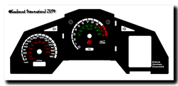
©Lockwood International 2014 - UK Futura inlay with voltmeter, L&R indicators and sidestand lightWith the new inlay nearly complete and sufficient testing of the modified dashboard to prove its reliability in day-to-day use, it’s now time to move on and complete the next stage of miniaturising the circuit board. The big grey box and wiring loom holding the Arduino Uno stays for the time being, but now it will house the smaller circuit board and Arduino Nano. Once thoroughly tested, the box and loom will disappear as the board finally gets mounted inside the case.

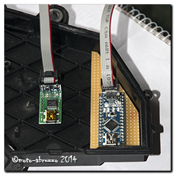
Aduino Nano and Pololu 1300 programmerThis time around the microcontroller will be programmed differently to speed up the start time and free up more memory space. For that I’m using a Pololu 1300 programming device ….. Something I’ve never done before, let’s hope I don’t fry it! If all goes well, that then leaves me an Arduino Uno spare and it would be rude not to find another Caponord related little job for it! So here’s the next project…..

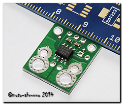
I’ll be installing the Uno and three of these naughty little puppies along with and LCD screen into the redundant grey case. Self-powered, it will measure current flow through the 30A rec/reg fuse and the two main 30A fuses simultaneously. The screen will Pololu ACS714then display measured and calculated data as well as storing the data onto an SD card mounted into the display. So it’ll be a data-logger as well!

The idea is to have the three ACS714 devices, wiring loom and a single multi-pole connector under the saddle. The unit will then simply plug into the connector and merrily measure away. A decent battery and memory card should make data logging for 2hrs + pretty straight forward. So watch this space ………


See ya later Indicator

While it rains, rains and rains some more, I’ve had time to complete the mods with respect to moving the warning/tell-tale lighting around on the dashboard. Now the Capo has a nice left AND right indicator repeater lights ….. and looks all the better for it. So to recap.

  1. Unused ABS light is now the side-stand light
  2. The side-stand light is now the low-fuel warning light
  3. The low-fuel warning light has new green LED’s and is now a right-hand indicator repeater.

Here’s another piece of video with all the lights working. You’ll notice that the fuel is already on reserve, hence the old side-stand light (now low-fuel) is on throughout the video. Sorry about the quality, but a dismal dark day and a smartphone don’t work so well together ….. and my cold hands adding the shake didn’t help! I’ll add a new page to the site shortly with details of how the circuits were rearranged.

While I waited for Youtube to upload the video, I took a walk down the road to see what damage had been done by the 24hr+ of solid heavy rain …………

…………. let’s just say the Capo nor the Rangerover are going anywhere soon. We don’t appear to have a road left for about a 30m stretch. It appears to be languishing somewhere down in the valley by the looks of it! Pics tomorrow. 😥

Tacho/Voltmeter live on the Caponord

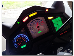
Up and running at lastPhase 1 is over, Phase 2 begins …….. yes, the reworked dashboard with voltmeter/tacho and fade-in/fade-out auto-dimming backlighting is off the workbench and finally onto the Caponord. I know it doesn’t look too inspiring at the moment, but it is only a prototype unit for development. The white tacho face is simply a temporary inlay printed on a piece of A4, so it better not get wet!

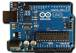
Arduino Uno V3Inside the box lives an Arduino Uno with a homemade interface board that switches and adjusts the signals to/from the dashboard as required. The single connector plugs into an additional fused loom that runs to the battery positive terminal. I’ve tried to build in safeguards against under/over voltage, battery disconnection and reconnection spikes and its own failure with regards to how the dashboard functions, hopefully most if not all eventualities have been covered …. fingers crossed!

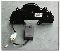
The little grey box .... I’ll run this setup for a while and try to iron out any other issues as they crop up, but what then? Well Phase 3 has already started in parallel with Phase 2! A new microcontroller board that uses the same chip, but with a footprint that is an astonishingly small 8% of the Uno has been ordered. Not only is it small, it also loses the peripheral bits and bobs that I don’t need – and that means much lower power consumption. I’m really hoping to get the whole thing inside the dashboard case if possible, but the worst case scenario will mean a small box fixed directly to the back of the dashboard – so no wiring loom or bulky connectors!

Where the ideas originated ..... the Kwak GT & GPZ's of the 1980/90 eraAs well as getting the inlay reprinted with the added voltmeter graphic, I’ve also decided on a little  re-arrangement of the existing graphics and functions. For example, why oh why is a ‘side-stand’ light prime-center of the display when it already has a safety circuit to stop you riding away with the stand down? ….. Magneti Marelli over-egging the pudding I think.

So the side-stand is moving down to the (unused) ABS lamp spot, the low-fuel then moves up to the side-stand lamp and the low-fuel light then becomes the right-hand indicator – as it should have been all along. Yes, a turn repeater for both left AND right hand signals!!!

Left AND right turn repeater lamps!

With all this in the pipeline, I can now source a decent place to have the new inlay card made. I’ve spoken to a couple of companies in the UK already, but I’ll keep looking around for a little while longer …….. do you know anyone you can recommend? If so, I’d like to hear from you.

 Last but not least, here’s another short piece of video with the panel working on the bike.


Dashboard upgrades

Evening folks, I thought I’d share this with you as the nights start to draw in and riding gives way to winter tinkering.

I mentioned over on the dashboard page about the upgrades hopefully working by spring next year. Well some of them have come along in leaps and bounds, so I took a snippet of video so you can see a dashboard work-in-progress strutting it’s stuff on the workbench. OK, I know that there’s no voltmeter markings on the inlay yet, just use your imagination for now! It’s actually showing 12.4v ……….

Now while I’m waiting for an oscilloscope to miraculously appear, I’ll leave the board bench testing for a while to see if the code or controller breaks, then fingers crossed, it’s on to the auto-dimming back lighting instead of the three fixed settings of useless, mostly useless and acceptable.